
The word "continuous" is hopeful in most contract documents. On paper, drawing the air barrier as a single line wrapping the building from foundation to roof may seem a perfectly reasonable thing. But, as many of us are already painfully aware, on paper does not equate to constructability in reality.
What happens is something we like to call decompression drift. The designer works out a condition that exists in three dimensions, flattens it into a two-dimensional detail so it can be printed and handed off, and then somebody in the field takes that flat drawing and blows it back up into three dimensions to understand how it gets installed. Information gets lost on the way down to the page, and whoever does the reinflating fills in those gaps with their own assumptions, which may or (more likely) may not resemble the assumptions the designer started with. Then go ahead and multiply that. A building envelope transition rarely belongs to one trade, so the reinflating actually happens several times over, independently, by brains that are likely filling in the blanks with a slightly different idea of what that 2D detail means in 3D.
The 1% That Undoes the 99%
Ninety-nine percent is a terrific score in most contexts, but construction isn’t one of them. An air barrier can be 99% perfect in the field of wall or field of roof and still fail because of what happened at the remaining 1%: transitions. That’s because an air barrier doesn’t perform as an average of the best and worst of its parts, it performs as well as its weakest area. The right product, right thickness, and right substrate preparation only matter if you also do it right at the tie-ins.
Here’s a handful of the 1% culprits we often see drag down the 99%:
Roof-to-wall and foundation-to-wall transitions. The drawings show the air barrier as a simplified, continuous line from one component to the next . What they do not show, or know, is that the different components are installed by different trades, and at different times in the construction schedule. If the roof air barrier is meant to lap onto the wall air barrier but the roof goes in first, the wall air barrier installer isn't going to work on a roof that isn't in their scope, and the lap gets built in whatever way the sequence allows, whether or not that aligns with the design intent, much less matches the drawings exactly. Foundation-to-wall is the same story, flipped upside down.
Dissimilar material transitions. The roof-to-wall and foundation-to-wall transitions are a question of who and when. This one is a question of whether the two materials meeting at that line were ever meant to touch. Membranes from multiple manufacturers may perform perfectly well in isolation but be chemically incompatible or have no tested method of adhering to one another. This requires close attention in pre-construction and reviewing submittals across multiple assemblies and trades, where submitted products may differ slightly from the basis-of-design.
Window and door openings. A rough opening is, by definition, a discontinuity in the air barrier. That means that the tie-in at the perimeter of the rough opening is both complex and critical. What earns these transitions a spot near the top of this list, however, is that it’s a repetitive detail. An issue with the continuity detailing on one is an issue with the continuity detailing on the other 99 on the building.
Structural and MEP penetrations. I-beams, anchors, and angles, oh my! These are direct penetrations through the air barrier, and they can be detailed accordingly without much trouble. The issue is that they often aren't detailed in the architectural set to begin with. They live on the structural or MEP drawings, and the architectural section shows an uninterrupted air barrier because nothing in that set says otherwise. Clash detection during design can catch that, if it happens, but we can tell you it certainly isn’t happening in the field. Once construction is rolling, clash detection resolution becomes on the fly detailing by the installers themselves.
Metal decks. Air barrier products are designed and tested against flat, continuous substrates. Metal decks are…wait for it, wait for it, wait for it…yep. Not flat; fluted. A detail that shows the membrane running into a flat line labeled "deck" leaves that entire exercise to be worked out on site. Solving this issue means thinking about the deck geometry in 3D, and designing pre-formed flute closures before the roof air barrier goes on above the deck, with a transition membrane rated to bridge corrugation or closed-cell foam below.
Soffits and parapets. Are soffits and parapets indoors or outdoors? Or are they playing both sides (and therefore good at neither)? Whether a soffit or parapet is meant to sit inside the conditioned envelope, with the air barrier wrapping the outside of it, or outside the conditioned envelope, with the air barrier and the other control layers isolating it from the interior conditions, is a design intent question. And either answer works. What doesn’t work is leaving the question unanswered. It’s a risk at any change in plane, but particularly at soffits and parapets because they stick out from the building — an architectural peninsula, if you will — and are exposed to outdoor conditions on multiple sides. That means the temperature inside a soffit or parapet tracks the outdoors much more closely than the rest of the wall does. If the air barrier is vague or discontinuous somewhere in there, air from the warm, humid side — generally indoors in winter, and outdoors in a hot summer — finds its way in, hits a surface that's running a much colder temperature, and condenses.
Divided We Build
None of this is really about bad workers. It's about how the work gets divided. Design drawings show the intent of continuity, but they rarely account for sequencing or constructability once that intent gets split among a dozen trades or spread across phases.
The crew that installs the air barrier is long gone by the time everybody else shows up to poke holes in it (or install rooftop equipment or cladding attachment, whatever you want to call it). Recapturing continuity means bringing the air barrier installation crew back once, twice, maybe more times depending on how many trades poked holes and how far apart their work was spread out on the construction schedule. It’s an expensive and undesirable game of hot potato that often gets swept under the rug altogether.
You can see exactly where this breaks down by looking at the shop drawings. Each trade's submittal shows that trade's own scope in careful, dimensioned detail, and renders everything "by others" as a vague, schematic suggestion. The transition, the one spot that depends on both sides being right, ends up drawn precisely by nobody, or assumed differently by everybody.
The Bill Comes Later
A continuous air barrier and a discontinuous air barrier cost approximately the same to construct. The real bill comes later.
Code Compliance. Energy codes are becoming increasingly performance-based. Under the old approach, specifying an air barrier and detailing it as continuous checked the box. Under current editions, air leakage rate has to be demonstrated using methods such as a blower door test. A building with a perfectly continuous air barrier in the documents can still come in over the compliance limit for any of the 1% culprits we mentioned above, and "compliant on paper" is of limited comfort while someone rips up completed construction to find them.
Energy Performance. The air barrier is what keeps the air you've paid to condition inside the building. A discontinuous one means exchange with the exterior climate — whether that’s warm, conditioned air “escaping” in a cold climate or warm, humid air infiltrating your AC-ed space in a warm climate, the mechanical systems are working harder to make up the difference either way. That shows up as higher heating and cooling loads year round, and more corresponding digits on the utility bills. Utility bills which will keep coming with hard-to-swallow totals until the air leakage is addressed.
Condensation Risk. Air leakage doesn't just move air, it also moves moisture, and a lot of it. When people think about moisture in an assembly, diffusion — water vapor slowly working its way through the materials themselves — is usually what comes to mind. Diffusion is real, but it's slow and relatively small. Air leakage carries far more water vapor and moves it far faster, through any gap it can find. Double whammy.
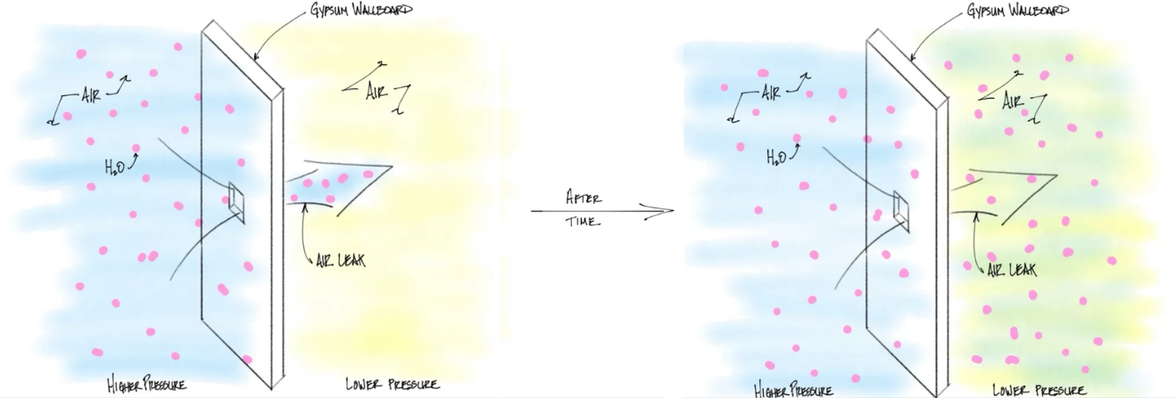
To add a layer, the physics behind energy performance and condensation risk are entangled. Old, leaky buildings were terrible on energy, but a lot of them never developed serious hidden moisture problems because all that leaking meant their assemblies were being passively ventilated. Moisture got in, sure, but it also had an easy way to dry back out. Tighten the envelope and that accidental drying goes away. With a continuous air barrier, that's fine, because the moisture isn't getting in to begin with. With a mostly continuous one, you've kept every path in and closed off the way out.
Owner Homework
While a lot of the issues are the culprit of assumptions being made in lieu of design direction, a surprising amount of it can be settled by what a building owner asks for and budgets for.
- Ask to see 3D isometric details for the genuinely complicated conditions. Even a 3D photo markup counts. Don't expect a crew to build in three dimensions something the design team couldn't be bothered to draw in three dimensions either.
- Coordinate shop drawings across trades, not just within them. From an owner’s seat this is difficult to do without help, but it’s important enough that we can’t cut it from the list. Asking for an interdisciplinary coordination drawings, or at minimum a requirement that overlapping trades' shop drawings get reviewed together at shared transitions, catches the gap between them before it's built instead of after.
- Make the preconstruction meeting mandatory, and focus on sequencing. Specifically, something that goes beyond a general kickoff meeting, where sequencing expectations can be set and conflicts can surface before they hit the field. The sequence needs to be unambiguous to everyone involved so that each trade knows what it needs from the one before it and after it.
- Budget for first-of-kind mock-ups. A field mock-up is the cheapest way to find out whether or not the detail on paper works in the sequence the trades will really use. At particularly tricky or unknown transitions — such as those that are worthy of receiving the 3D isometric details mentioned above — have a to-scale mock-up built on-site by the actual trades who'll perform the work. Better yet, have the designer on-site while it’s being built to review it and recommend any adjustments needed if the sequencing or detailing in reality is unachievable as drawn on paper.
- Separate qualification testing from production verification, and test along the way. We categorize construction testing by intent. Qualification tests — laboratory work, field mock-ups, and first-of-kind installations — are front-loaded in construction and confirm that the design is constructable and that the trades understand what's being asked of them. Production verification is ongoing sampling, confirming that what was proven achievable is actually being achieved. Hate to burst your bubble and point out that a blower door test at the end of a project is neither of these, but…pop! It may confirm a result at the end of construction, but it doesn’t leave much room to fix one if it’s not the one you wanted to hear. Testing repetitive details, like a window or door mock-up assembly, for air tightness at the start of construction, and then periodically as construction goes on for assurance purposes, catches a would’ve-been systemic problem that has to be remedied on a fraction of the conditions.